http://cylonrobot.blogspot.com/feeds/posts/default

Wednesday, January 26, 2005

An excellent Q & A from the Seattle Robotics Society mailing list (updated)

Jeff Birt wrote me a great email on the Seattle Robotics Society mailing list and I thought I would share his questions and my answers to the blog community as a whole:

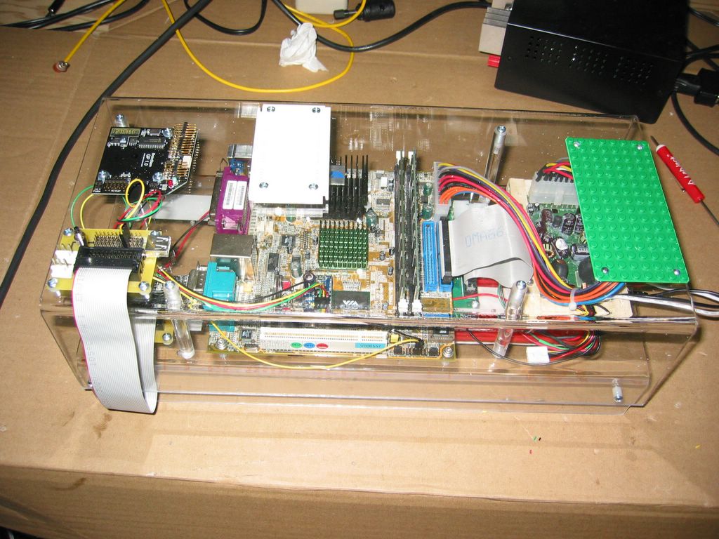
Are you pleased with your choice of EPIA mb?

I'm pleased with my Via EPIA 5000. While it is "only" 500 MHz, that's more than enough CPU for my needs. The only reason I would change would be to move to the smaller 10 cm x 10 cm Nano-ITX form-factor when it comes out. Even then, I'm going to have to evaluate it first because the Nano-ITX promises to be more expensive and more power hungry than the Via EPIA 5000.

Does the fan-less 500 MHz board perform well analyzing two video feeds, etc.

I haven't attempted to analyze two video feeds off of it. Light video analysis (1 fps, orange cone color and shape detection) is working well and that is all I needed to accomplish for Robo-Magellan so that is all I tried. It should have enough CPU to exceed this level of processing by a significant margin, but video processing can get expensive very quickly so you could easily overwhelm the CPU depending upon how complex your algorithm is and how efficient your code is.

What things are you including in your XPe build? What components do you consider essential?

I've just recreated my image to take advantage of the new XPe SP2 bits. I've carefully cataloged the choices I've made and I intend to write it up thoroughly on my blog. I haven't had a chance to write the article yet though and I have a lot of other stuff going on in my life at just this moment so I won't get it written until next week. If you're in a hurry, drop me an email directly and I'll sent you my rough notes.

Any gotchas?

There are unfortunately plenty of gotchas when going through the learning process of how to set up your environment and how to get features such as the Enhanced Write Filter (EWF) working and getting XPe to boot off a Compact Flash card. Again, I'm planning on writing this up in an blog article next week. Unfortunately, I don't have clear rough notes on this yet so you'll just have to wait

I was planning on putting TAP on a BartPe cd. How are you handling this?

I have a hard drive that I attach to my motherboard that I use to download the XPe image and run FBA (First Boot Agent) off of. This hard drive has two partitions, C: contains my XPe image and D: contains a full XP Pro image. I boot to the D: XP Pro image to run TAP.

Lee asks, "What about i2c or SPI? Does this board have those?"

I use an Acroname Brainstem for my IO (it attaches via RS-232 to the motherboard). The Brainstem has two headers for I2C.

Fred Kerr asks, "How are you powering the board?"

I use two Sub-C RC card battery packs (6 cells each) wired together to make 12 cells total, a PW-80 DC to DC power converter (90+% efficient) from ITuner, and an Electrifly Triton charger.

Sunday, January 23, 2005

Look at that, control the ER1 wheels without the ER1 software...

I've rebuilt my Windows XP Embedded image using the updated XPe Service Pack 2 release. All the basic electronics are mounted, including my repurposed ER1 stepper motors/wheels and the ER1 control box that drives them. I was getting excited that I was pretty close to finishing my indoor chassis.

Ah, but another wrinkle appears -- the ER1 software really, really doesn't want to sit on top of XP Embedded. First it insisted that it needed ~150 MB of free space to install although to my measure, it only takes up about 20 MB and 15 MB of that are graphics and sound files it uses for vision and audible feedback. After I managed to trick it into place, it started working for a while and then started throwing GPFs. Sigh, it started looking like I was going to have to chuck the ER1 motors and start over.

While I was reading Evolution's forums to see if there were updated drivers I should be using, I stumbled upon a fortuitous post. A gentleman by the name of Yau Lam Yiu had already reverse engineered the ER1's serial control protocol, complete with a nice Visual C++ program demonstrating how to control the ER1 motors! Very nice work, the code is simple and readible. Now to port it over to Managed C++ and add it to my library of devices...

Thursday, January 20, 2005

Some forward progress!

Below are a couple of snapshots of the "mostly finished" chassis rework for Cylon. I've finished the cabling to attach a USB device, the Brainstem, and the on button as well as added a few mounting areas to the sensor plane.

OK, I'm ready to test -- I connect the power, press the on button, and....nothing. Hmm, it seems like I'll have to go through and do some additional wire testing, line by line. In all fairness, this weekend I snapped a few cables off my ATX power supply cable while working on the chassis. While I have replacement parts on order that I can use to make a more solid power cable, I did a little "questionable repair" last night that I was hoping would hold me over until the parts arrived. Perhaps that didn't work out as well as I had hoped...

Side view of the same Posted by Hello

Aerial view of the finished brain & sensor planes of the new Cylon chassis Posted by Hello

Monday, January 17, 2005

You're using *what* OS to run your robot?

Yes, Virginia, I'm using Windows. Windows XP Embedded, specifically. I want an environment where I can write the logic for my robot using C# & the .NET Framework which is the programming environment I use in my day job for which I've developed quite a liking. I don't want to load up my robot with my 40 kilogram Dell Dimension, heck I don't even want to load my robot down with a 10 kg laptop. I want a small to medium sized robot.

The first path I followed was CMU's PPRK (Palm Pilot Robotic Kit) to which someone had attached a Pocket PC to rather than a Palm. This was very cool and motivating and a few hundred dollars and a couple of weeks later I was up and running. But I rapidly hit limitations:

  • It's harder to write .NET code for a Pocket PC

  • Many of the APIs are missing or limited, I couldn't write libraries very easily, and some key OS apis were missing (DirectShow & at the time various networking APIs).

  • It's really hard to upgrade a Pocket PC to a new version of the .NET Framework

  • With the .NET Framework improving rapidly, even today ~ five years after its first introduction, I found the "burned into the ROM on the device" approach very limiting. Pocket PCs are consumer devices, meant to be used and disposed rather than continually upgraded.

  • Drivers are hard to come by

  • A robot is nothing without its devices. While there was good support for the Acroname Brainstem, finding drivers for various network cards, cameras, GPSes, etc. was really tough. I ended up selecting from a list of very limited hardware suppliers whenever I wanted to try and add a new device. And with expansion ports basically limited to one PCCard or one SDCard, I wasn't able to add the number of devices I wanted.


    The answer, I was told by people in the know, was to eschew the Pocket PC -- which is meant to be a consumer organizer -- and get a hardware platform that runs Windows CE. Aren't they the same I say? No, one is a consumer hardware device, the other is a development environment like Windows XP that you can customize, update, etc.

    Now comes the search for a Windows CE enabled platform, a place to buy a license of Windows CE, etc. Well, let me cut to the quick. It turned out to be very expensive ($500, Quantity 20+) and none of the Windows CE resellers were terribly motivated to take on a custom, one off job for some robotics dude. Many months of discouragement later, I shrugged off the whole Windows CE and Pocket PC thing as an idea that sounds better than it is in reality.


    But wait, there is hope after all!


    Why not use Windows XP? It turns out there's a whole sub-culture in the PC world around making small, energy efficient PCs and sticking them everywhere. These motherboards are called Mini-ITX and they're fully capable x86 motherboards.

    A very cool feature of XPe is that you can ditch the hard drive too. XPe has a "Target Builder" tool that lets you pick and choose exactly the functionality you want, omitting all the files you don't need. It also has a really important feature called the Enhanced Write Filter, or EWF, that lets you mirror your file system in RAM so that any writes you make are cached in RAM until you choose to commit them or throw them away (generally at shutdown time). This is really important when using static ram (like Sandisk CompactFlash cards) because while static ram can be written to, it can only be written to a couple of hundred thousand times. You laugh, but that one little bit on the disk that's constantly being "ping ping pinged" to update some timestamp or somesuch will cause a Compact Flash card to fail if you boot an operating system off of it and give it free reign to write whenever it wants.

    After some playing around it turns out that I am able to load a full XPe image complete with all the networking functionality and utilities I want, Remote Desktop for remote management, and a bunch of other stuff onto a 512 MB CF card with enough room to load the entire .NET 2.0 Framework and still have plenty of space to store my robot applications and data logs. Since 512 MB CF cards are pretty darn cheap these days ($36 according to PriceWatch today), this makes for a pretty good and inexpensive solution.

    The cool thing is there may be some limitations when using XPe in terms of functionality or driver compatibility, but I haven't found any yet. I'm able to use my Logitech QuickCam, a couple of different USB GPSes, any of my 802.11b wireless adapters, etc.

    When writing add-on libraries for my robot, I've been able to use all the networking libraries of .NET, hook into DirectShow to get 30 fps uncompressed video frames off my QuickCam for image analysis, shuttle my real time sensor readings out to a laptop so I can do cool real time telemetry, leverage the built in RS-232 IO and GZip compression classes, etc. Basically all the tools and libraries a professional developer uses on their development PC.

    This plus the ability to use a full IDE (Integrated Development Environment) like Visual Studio with remote debugging (on the robot itself) and all the tools you need to do a solid coding job like source control integration and a unit test framework. Pretty cool, nu?

    So, what are the pros and cons of using XPe for a robot?


    Pros

  • Runs on cheap, low power, small form-factor PC motherboards like the $95 Via EPIA 5000

  • Compatible with Windows XP drivers, so your device choices aren't limited

  • Has all the powerful libraries that you'd expect in a desktop development environment

  • Allows you to use a powerful programming environment with debugging, source control, etc.

  • Can easily test your code on your desktop PC running Windows XP without needing to use an emulator

  • Can load XPe in a virtual machine (like VMWare or Virtual PC) and connect to your microcontroller from the XPe VM

  • XPe evaluation is a free download


  • Cons

  • I *still* have not found an embedded reseller willing to sell me a Q1 license for XPEmbedded, so your "evaluation" image has to be rebuilt every 90 days.
  • While power efficient, the Via EPIA 5000 still chews power quickly compared to a microcontroller. I use two 1900 mAh NiCD battery packs to power my motherboard for ~30 minutes


  • So, that's my experience to date. I'm continuing to contact XPEmbedded resellers to try and find someone willing to sell Q1 licenses to robotic hobbyists. If I do, I'll let you know where you can get a license here. If you want more detailed information, such as what exact parts I ordered for my motherboard et al or what I included and omitted in my XPe image, drop me an email and I'll be happy to help you out.

    The proof of whether this is a good idea or just another flake will be in next year's Robo-Magellan contest. I'm still of the opinion that solving a good, hard challenge like that one will stress software as much if not more than hardware. My challenge is to make sure that both my hardware and software are up to the task. Last fall, problems in my networking signal took me out of the race. I don't intend to let a hardware failure do the same next time.

    - jcb

    How to you get a PC (or a Pocket PC or a Palm) to talk to all that robot hardware?

    So you want to create a robot. You've got a great idea -- you're going to use that old Palm Pilot you have sitting around, or maybe a Pocket PC, or maybe you agree with Via and think a Mini-ITX PC motherboard is going to 'be all that'. Heck, you even have an old set of rollerblades you haven't used in two years, an erector set, and some windshield wiper motors you've been saving from your '57 Chevy for the day when you knew they would come in handy.

    So you have your computer of choice and your compiler and you've written your first line of code, "Console.WriteLine("Hello, Robot");" and compiled it and it's all very exciting. But there's a missing piece. How can you get this computer of yours to talk to the windshield wiper motors? OK, more seriously, how can you get it to talk to a couple of servos, maybe a RC car's speed controller, perhaps even a Sharp IR distance sensor or a digital compass?

    The glue that you're going to need is called a microcontroller. A microcontroller is a modern day marvel -- it combines a very small computer, RAM storage, and low level input/output lines into a single cheap, small chip. They're really useful for robotics because they're smart enough to talk to a PC using a high level communication protocol like RS-232 or sometimes even USB or Ethernet while at the same time they can talk to hardware devices using a much lower level protocol like pulse wave modulation (PWM), analog (voltage) to digital converters (A/D converters or just A/D for short), Digital I/O, and a microcontroller-specific serial bus called I2C.

    Here's a brief overview of each type of signal:

    PWM (Pulse Wave Modulation)
    PWM takes the current on a wire and turns it on and off rapidly in pulses. It has a frequency (how many times a second could it potentially go on and off) and a duration (what % of the time is it on versus off).
    PWM is commonly used in robotics to control "how much" of something since it's much more reliable to measure PWM pulses than minute fractions of a voltage change due to how microcontrollers work. You'll frequently see PWM used to control the position of a servo, the speed of a motor, or the intensity of an LED.

    A/D (Analog to Digital converters)
    A/D takes a current on a wire and measures it's voltage. Is it at 3.1V or 5.0v or 0.5v?
    A/D is commonly used to measure 'resistive' sensors, like cadmium sulfide light detectors or temperature sensors. It's also useful when using the Sharp IR distance sensors (GP series).

    Digital IO (I'll call it DIO)
    A DIO port are kind of like a "dumb" A/D port in that it generally measures if the voltage on a wire is < 2.5 V (off) or > 2.5 V (on). Even this "dumb" reading is useful for simple inputs like 'is that button or switch pressed' for an on button or a whisker bump sensor. They are also generally configurable as output ports where they can be used to do things like turn on an LED. Many times, using microcontroller code that's tightly written, they can also be used to build up higher functionality by switching on and off very rapidly -- from making primitive music on a buzzer to "bit-banging" (AKA rapidly banging out bits, generally by dedicating all the microcontroller's CPU cycles to this one function) a higher level communications protocol like RS-232 or USB or I2C.

    I2C
    I2C is a microcontroller serial protocol that is used much like RS-232. The reason I2C exists is it is simpler to implement on a microcontroller and it can be used as a "multi-master bus", AKA more than one device can be attached to the wire (like USB). I2C is commonly implemented in hardware on microcontrollers and so it makes a good choice to be used when hooking multiple microcontroller assisted sensors together. There are a plethora of similar microcontroller serial protocols out there that compete with I2C, but I'm only talking about I2C here because it's the protocol that the devices and sensors I like use (see Devantech and all their cool stuff). You can debate which one is "best" just like all the other "best of/shudda used" debates out there, but I'm just interested in making my robot work, nu?


    Alright, do you have a point already?

    Yes I do. I'm just warming up to it, OK?

    After a lot of searching and spurious buying of excess equipment that took my money and now takes up my shelf space, I settled on the Acroname Brainstem the way I attach my "brains computer" (AKA Mini-ITX PC or Pocket PC or Palm Pilot) to my robot. Why did I choose the Acroname Brainstem?

  • It has a good selection of ports


  • The Brainstem GP comes with a decent selection of ports, enough to make a moderately complex robot. It has 2x I2C, 4x PWM, 5x DIO, 5x A/D ports, and 1 RS-232 port. In other words, I can attach it to my computer, four servos, a digital compass, two IR range finders, a gyro, and a two-axis accelerometer. Yep, you can definitely do some non-trivial robotics there.

  • It has a great programming interface


  • I was first attracted to the Brainstem because it was being used by both Palm Pilots and Pocket PCs to drive cool robots. Back when I was first starting, I was totally convinced that a Pocket PC was going to be my robotic brain. I was wrong about that, but I ended up being right about the Brainstem. With good documentation and great libraries and sample code for WinCE, Windows, Palm OS, and Linux, the Brainstem is easy to use from a variety of programming environments and tools.

  • It has a fast slave mode


  • Ah, this is an important and not necessarily obvious one. If all you want your robotic microcontroller to do is feed data back and forth from your "brain computer", you want it to do so rapidly. Most microcontrollers out there (Basic Stamp, OOPic, Handyboard, etc.) concentrate on writing programs that will run when a computer *isn't* attached. While you can do so on the Brainstem too, Acroname has put a lot of effort into making sure the Brainstem is a good "router", AKA a device that "routes information" between places without getting in the way.

    Also, the Brainstem can use RS-232 at 112kbaud and it has an extremely low protocol overhead so you are getting mostly data over that link. Some microcontroller choices don't do a good job with this. For instance, the controller that comes with the ER1 system has a "fast USB" connection back to the host computer, but their wire protocol is, ah, lacking and they didn't exactly work on the efficiency as a #1 priority. Trying the best I could, I was only able to get 3 readings per second off my ER1's A/D ports when I had other things going on at the same time (like controlling the motors, etc.) which is completely insufficient for writing routines like obstacle detection and avoidance.

  • It's well supported


  • You don't really appreciate a knowledgeable dude answering the phone on the second ring or responding to an intricate forum post at 11 PM at night until you really need it. In the dozen or so times over the past few years that something around the Brainstem has stumped me, Mark or Steve from Acroname have cleared it up within 12-24 hours. You can't beat that.

  • It's expandable


  • Need to control some high amp motors? You can daisy-chain a Brainstem Moto to a Brainstem GP (General Purpose) over the I2C bus. Need to add another 5 A/D ports? Daisy-chain another Brainstem GP or attach one of the many I2C controlled slave boards out there.

  • It's cheap


  • $79 is a lot better deal than the cost of getting ahold of a C compiler, microchip programmer, and making up some PCB boards. Believe me, I know :-) With the support and documentation and out of the box functionality you get, it can't be beat.


    Well, that's it. I think you get the drift, I like the Acroname Brainstem. When I get off my duff and finish off my work, I'll be publishing a Managed C++ wrapper for the Brainstem SDK that makes it really easy to take advantage of the Brainstem from any managed programming language like C# or VB.Net or any of the 22 or so others out there.

    Sunday, January 16, 2005

    How do you carry signals and power in a multi-plane robot chassis?

    I'm converting Cylon over from a simple single-level robot to a multiple level robot, as stated in a previous entry. I'm doing this to give me more room to mount sensors, get more distance between sensors and logic (to help deal with electromagnetic interference), and to help protect the components better from damage.

    This introduces a new problem though. How do I carry signals between levels? I need to carry power and various IO signals like USB, I2C, RS-232, PWM, etc. I could just run a new cable between levels for each signal -- if I need to carry USB from the motherboard (logic level) down to the Evolution ER-1 controller (drivetrain level), just drop a USB cable through the polycarbonate via drilling a hole. But now I need to carry an RS-232 cable from the motherboard to the Brainstem (sensor level), etc.

    In looking at all the various types of IO signals I need to carry a pattern emerges. All of the ones I'm currently using are Gnd/+5V/Signal 1/Signal 2 or just Gnd/+5V/Signal. For instance TTL RS-232 (as used to control the Brainstem) is Gnd/+5V/TX/RX. USB is Gnd/+5V/Diff1/Diff2. PWM is Gnd/+5V/PWM. So, what if I could use a ribbon cable to carry any of these types of signals? Alright, this is the challenge I've set out to solve, and here's a CAD drawing of my first attempt:


    The concept is simple -- use a 26 pin ribbon cable to carry Gnd, +5v, and 12 signal pairs. Supplement this with a Molex 0.156" three prong connector to carry heavy current loads where needed (from say batteries to PC power converter). Create a PCB that breaks the signals out from the ribbon cable into 12 sets of Gnd/+5v/Sig1/Sig2 that are connected to 4 x 0.100" header pins so that you have a standard connection to the IO board. And, uh, don't worry about interference for now since the distances traveled are short and, well, you have to start somewhere :-)

    A short order from ExpressPCB.Com later, and you have three PCBs, each of which contains two of these boards (they have to be cut apart, I use a Dremel with a Carbide Cutting Wheel) for a total of six PCBs ready to build for $59 total. A few parts from Jameco, and some soldering (about 15 minutes or so) and voila:


    Note: There are two sets of holes for a USB-A header that attaches to the IO1 lines. I couldn't tell from documentation which side was ground and which side was +5v, so I ordered a board with both configurations. After a little experimentation, I'll update the board to have only one set of holes with the proper power orientation. If you'd like to play with the PCB now, download the PCB software from ExpressPCB.Com and load this file.

    - jcb


    I've received some feedback in email from Larry Barello, a gent who helps out quite a bit at the Seattle Robotics Society. He recommends that I add a supply capacitor and perhaps even a power regulator to each board to minimize interference over the longer wires that a bus like this implies. Since I already have my boards in hand, I'm going to give them a shot as is, but be forewarned to those of you thinking of ordering a couple of your own that you may want to alter the design per his feedback.

    - jcb

    Saturday, January 15, 2005

    Simple tips of the day

    Hey, two tips I've recently learned that I'd like to share:

  • Silicone Sealant is your friend.

  • The GE Silicone II sealant you can find at your local hardware store is waterproof, a great insulator, withstands up to 400°F, dries in 30 minutes, goes on cold, and withstands vibration pretty well. This is a great alternative to hot melt when you need to seal or add vibration resistance to something. For instance, the DC to PC power converter I purchased looked like it would work great for a car but many of its components looked like they would shake loose when run in outdoor terrain on my monster truck chassis. I didn't want to use hot melt because some of the components (5V power regulator for instance) would get hot in operation and I didn't want the hot melt becoming viscous.

  • If you're a software developer who wants to work on robots, ask your sister-in-law to marry a machinist

  • Over the holidays, my sister-in-law and her new husband, Gene McDonald, came over and visited for a couple of days. Since I write code for a living, I've always struggled with my tools, from which solder to buy to how to make a really good hole with my drill press to how to cut plastic without melting it. Gene, who does amazing things with tools for a day job, was able to clear up a lot of little, stupid things I was doing and show me a lot of cool tricks in the space of a few days. On a personal note, as an only child it felt pretty cool to have a brother (inlaw or not) who could come by, slap me upside the head, and show me the right way to do things.

    Multi-layer robot base

    Winter is here in the Seattle area, and that means cold and rain. Cold and rain means that I don't get outside to run Cylon around my block nearly as much. To keep me moving forward in the interim I've been working on an 'indoor' base for the robot which is keeping me busy, but has kind of limited my progress.

    The first iteration of Cylon's chassis is built on the Tamiya TXT-1 RC Monster Truck. While this works extremely well for outdoor environments, its turning radius of 4' just doesn't cut it in my kitchen or living room. I need a base that can make short or even in place turns and this means differential drive where the wheels on each side can turn independently -- like a tank instead of a car. I decided to repurpose the parts of my Evolution Robotics ER-1 chassis for my drivetrain since the ER-1 comes with a couple of nice stepper motors with wheels and a control box that drives them from USB. In some previous work I had already written a C# wrapper for the ER-1's USB command protocol, so this was perfect.

    Since I'm redesigning I decided to fix two other problems with the first Cylon chassis design. All of Cylon's components (motherboard, power supply, Brainstem, sensors, etc.) except for the drive train were stored on a single layer. This made the mounting platform very crowded and chaotic and it also provided no protection in case the robot rolled over onto its side or its top. While the TXT-1 chassis is very hard to roll due to its excellent suspension, in working up to the Robo-Magellan contest I was constantly haunted by CMU's experience in the Grand Challenge. A Hummer is also very hard to roll, but a few weeks before the Grand Challenge a software glitch managed to induce a roll of the Hummer smashing key instruments and significantly setting CMU back in their progress.

    So this next chassis design had to handle three goals:

  • Allow a switch from external (TXT-1) to internal (ER-1 repurposed) drivetrains, preferably easily and in just a minute or two.

  • Provide multiple layers to attach components so I could get more room to make a cleaner design and allow me to do things like separate the logic (motherboard, power supply, CF drive) from the sensors (compass, GPS, camera, IR distance sensors)

  • Provide side and top roll-over protection


  • During the design process, three other side goals came out:

  • Allow batteries to be recharged in place, so I didn't have to take things apart and remove the batteries for every charge. With multiple layers, this was going to be more of a chore than before.

  • Provide sufficient distance between the logic layer and a top mounting layer so that sensors like the compass and the GPS unit that need magnetic and electro-magnetic separation for signal clarity have the necessary separation. I had serious debugging issues with my compass in the days before the Robo-Magellan contest that turned out to be interferance between the metal of the wires and motherboard with the local magentic field.

  • Come up with a simple way to shuttle power and data signals of various types (PWM, I2C, USB, RS-232, simple analog & digital voltages, etc.) between layers.


  • The approach I decided to take is to build the custom chassis out of 1/8" polycarbonate. Polycarbonate is relatively light, extremely tough, very crack resistant, and pretty darn cheap. Instead of gluing pieces together for the 90° turns which would introduce a failure point for side impacts, I had the plastic bent instead. Everything is attached together using screws (per excellent advice in Robot Building for Beginners) and tapped holes in the polycarbonate.

    One thing I quickly learned is while polycarbonate sheets are cheap (around $10 per layer, cut to specifications at my local TAP plastics store) asking the store to make the bends for me added up quickly (at $7.50/bend, two per sheet) and took time (2-3 business days for them to process). Since I was making multiple layers, it turned out to be a better deal for me to buy the parts from TAP Plastics that I could use to make my own plastic bending tool at home.

    Well, that's enough for now. I promise to be a little more on the ball and get my blog caught up to all the things I've been working on over the past few months.

    - jcb